
When designing PCB circuits or selecting components for electronic projects, engineers often face a critical question: which side should use pin headers and which should use female headers? While the title suggests a choice between them, it's important to understand that pin headers and female headers are complementary components that work together as a mating pair in connector systems
This comprehensive guide will help you understand their roles in connector systems, how to decide which component goes on which side of your connection, and best practices for designing reliable board-to-board and board-to-module connections.
What Are Pin Headers and Female Headers?
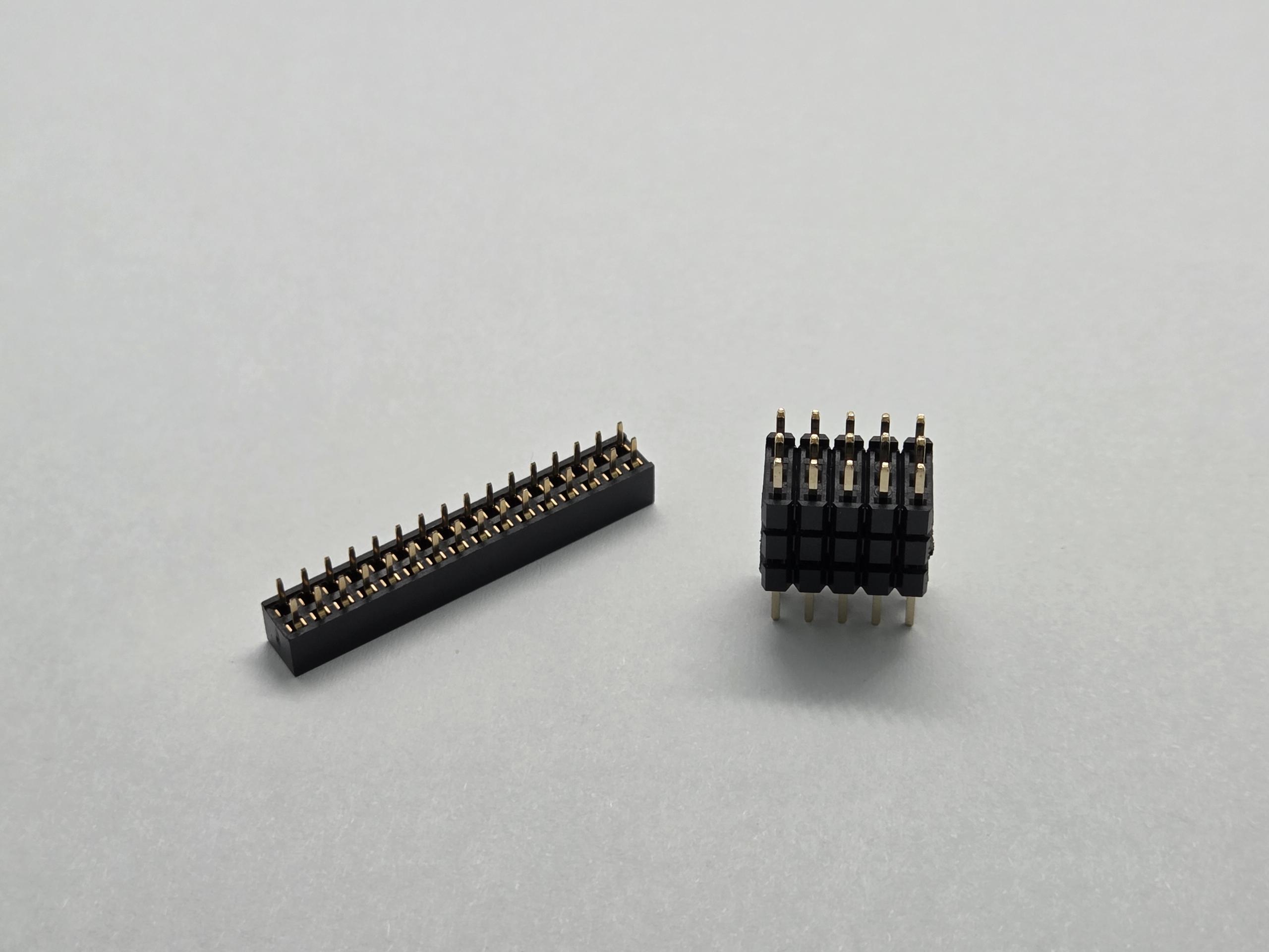
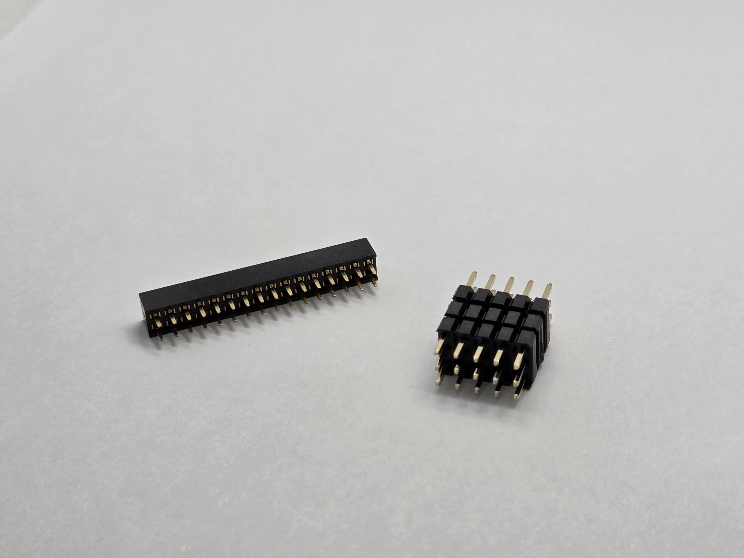
Pin headers and female headers are fundamental components in electronics that form a complete connector system. They always work together as mating pairs - the pin header (male) on one side connects with the female header (socket) on the other side, creating reliable electrical connections for circuit boards and modules.
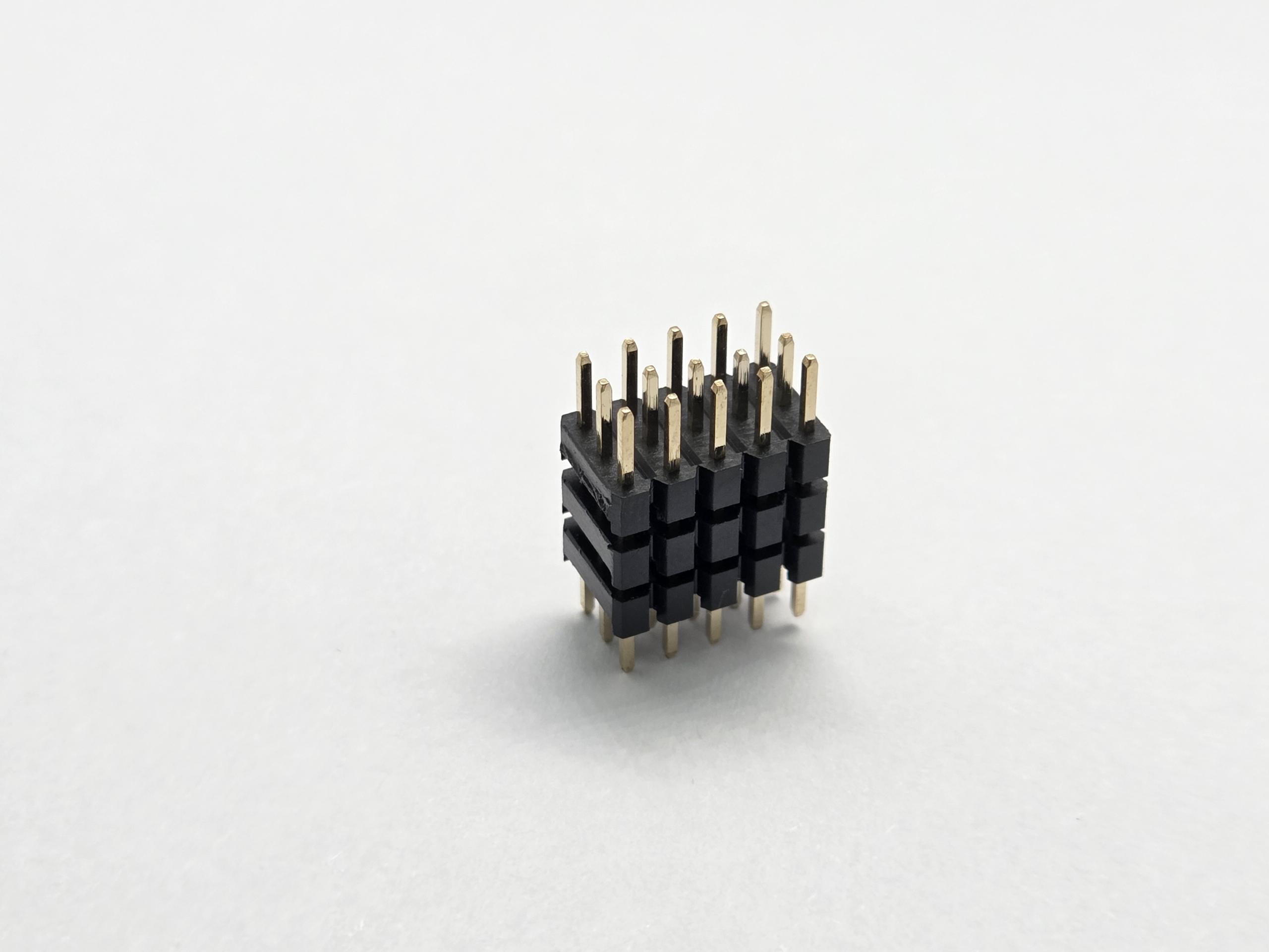
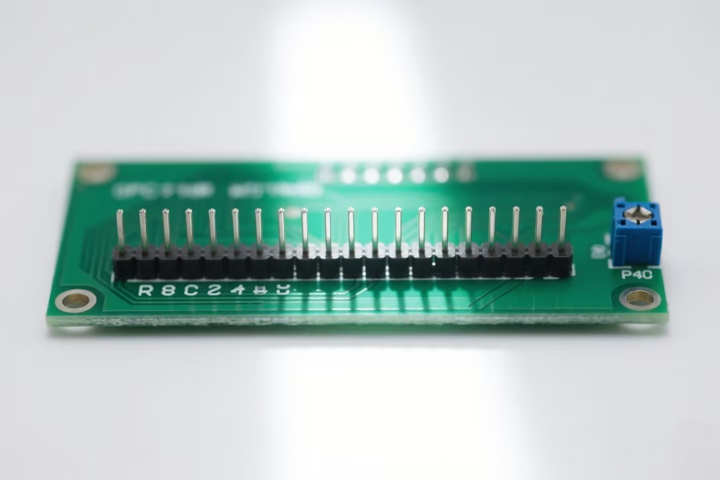
Pin Header (Male Connector): A pin header, also known as a male connector, consists of a row of metal pins protruding from a plastic housing. These pins are typically square or round in cross-section and are designed to be inserted into corresponding female sockets. Pin headers are commonly soldered directly onto PCB boards as fixed connection points.
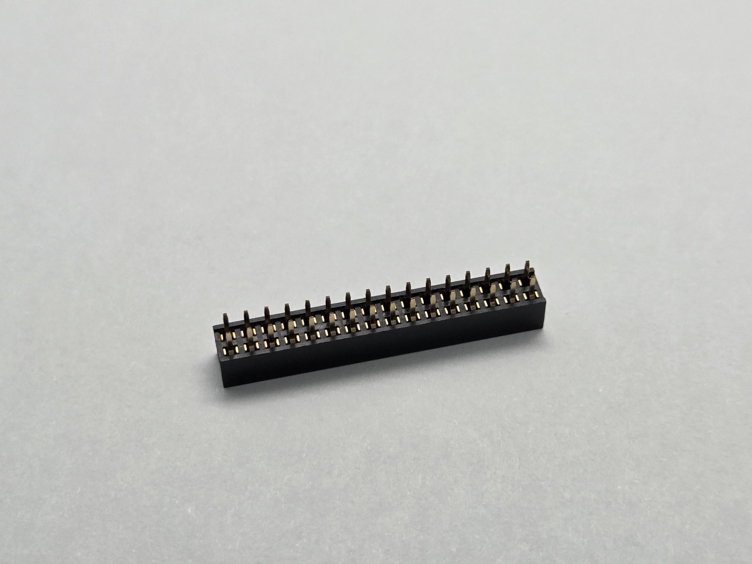
Female Header (Socket Header): A female header, or socket header, features internal metal spring contacts housed in a plastic body. These sockets are designed to receive and grip the pins from a male pin header, creating a secure electrical and mechanical connection. Female headers allow for easy insertion and removal of modules or components.
Physical Structure and Design Differences
Understanding the structural differences between pin headers and female headers is essential for proper connector selection and application.
Pin Header Construction
Pin headers feature a straightforward design with metal pins extending from a plastic base. The pins are typically made of brass or phosphor bronze with gold or tin plating for enhanced conductivity and corrosion resistance. Common configurations include:
• Single-row and dual-row arrangements
• Straight (vertical) or right-angle (90-degree) orientations,DIP or SMT
• Pin lengths ranging from 7.0mm to 60.0mm
• Standard pitch sizes: 5.0mm,4.0mm,3.0mm,2.54mm,2.2mm,2.0mm,1.27mm,1.0mm and 0.8mm.
Female Header Design
Female headers incorporate a more complex internal structure with spring-loaded contacts that provide reliable grip on mating pins. Key design features include:
• Precision-machined contact springs for consistent insertion force
• Plastic housing materials (PA6T, LCP) with high heat resistance
• Contact retention systems to prevent pin pushback
• Multiple row options for high-density applications
Common Pin Header Pitch Sizes and Specifications
Pitch size refers to the center-to-center distance between adjacent pins and is a critical specification when selecting connectors.
2.54mm (0.1 inch) Pitch - Industry Standard
The 2.54mm pitch is the most widely used standard in electronics, particularly popular in:
• Arduino boards and shields
• Breadboard prototyping
• General-purpose development boards
• Industrial control systems
This pitch size offers an excellent balance between pin density and ease of use, making it ideal for both manual soldering and automated assembly.
2.0mm Pitch - Compact Design
The 2.0mm pitch provides a 20% space saving compared to standard 2.54mm headers, suitable for:
• Space-constrained applications
• Portable devices
• Compact sensor modules
• High-density I/O requirements
1.27mm and Smaller Pitches
For maximum density applications, smaller pitches like 1.27mm, 1.0mm, or even 0.8mm are available, commonly used in:
• High-speed signal applications
• Multi-channel data acquisition
• Miniaturized medical devices
• Advanced computing modules
Pin Header Electrical Characteristics and Performance
As a professional connector manufacturer, we understand that electrical performance is paramount in connector selection. Here are the key specifications:
Current Rating
• Standard pin headers: 1A to 3A per pin (depending on pin size and plating)
• High-current variants: Up to 5A per pin available
• Derating factors: Consider ambient temperature and current distribution
Voltage Rating
• Typical working voltage: 250V to 500V AC/DC
• Withstanding voltage: 1000V to 1500V (test condition)
• Insulation resistance: ≥1000MΩ at 500V DC
Contact Resistance
• Gold-plated contacts: ≤20mΩ (typical 10-15mΩ)
• Tin-plated contacts: ≤30mΩ
• Long-term stability: Minimal resistance change over insertion cycles
Durability and Lifespan
• Pin headers (as fixed connectors): Designed for permanent installation
• Female headers: 500 to 10,000 mating cycles depending on quality grade
• Gold plating thickness: 3μ" to 30μ" for extended durability
Typical Applications and Use Cases
Deciding Which Side Gets Pin Headers
In a connector mating pair, pin headers (male connectors) are typically installed on the side that serves as the fixed, permanent base. Common applications include:
• PCB Board-to-Board Connections: As the male connector in mating pairs
• Module Interfaces: Arduino shields, Raspberry Pi HATs, expansion modules
• Test Points: Debug and programming interfaces (JTAG, SWD)
• Ribbon Cable Termination: IDC connector interfaces
Deciding Which Side Gets Female Headers
On the opposite side of the pin Common Pitch Sizes headers, female headers (socket connectors) are installed on the removable, modular components. This configuration allows for easy assembly and maintenance:
• Socketed Modules: Sensor modules, communication modules, daughter boards
• Stackable Connections: Multi-layer board stacking solutions
• Field-Replaceable Components: Easy maintenance and upgrades
• Development Platforms: Breadboard-compatible prototyping
Industry Applications
Both pin headers and female headers serve critical roles across industries:
• Consumer Electronics: Smart home devices, IoT sensors, wearables
• Industrial Automation: PLC controllers, sensor networks, HMI panels
• Automotive: Dashboard electronics, infotainment systems, diagnostic ports
• Medical Devices: Patient monitoring equipment, diagnostic instruments
•Telecommunications: Network equipment, signal processing boards
Installation Methods and Best Practices
Pin Header Installation
Through-Hole (THT) Mounting:
1. Insert pin header through PCB holes
2. Secure with tape or fixture to maintain perpendicularity
3. Solder using wave soldering or hand soldering
4. Inspect for cold joints and bridging
Surface Mount (SMT) Assembly:
1. Apply solder paste to PCB pads
2. Place pin header using pick-and-place equipment
3. Reflow solder in controlled temperature profile
4. Verify alignment and solder quality
Female Header Installation
Key Considerations:
• Ensure precise alignment with mating pin header before soldering
• Control soldering temperature to prevent plastic housing deformation (≤260°C peak)
• Maintain consistent height across multiple headers for proper mating
• Use alignment jigs or fixtures for multi-row installations
Common Installation Errors to Avoid:
• ❌ Excessive soldering temperature causing housing melt
• ❌ Misalignment resulting in mating difficulties
• ❌ Insufficient solder creating weak joints
• ❌ Pin damage from rough handling
Quality Factors and Supplier Selection
As a connector manufacturer with over 25 years of experience, we emphasize these quality criteria:
Critical Quality Indicators
Plating Quality:
• Gold plating thickness uniformity: ±0.5μ" tolerance
• Adhesion test: No peeling under tape test
• Salt spray resistance: 48+ hours for gold, 24+ hours for tin
Housing Material:
• High-temperature plastics (PA6T, LCP, PBT)
• Flame rating: UL94 V-0 minimum
• Dimensional stability: <0.1% shrinkage
Dimensional Accuracy:
• Pin position tolerance: ±0.05mm to ±0.10mm
• Pitch accuracy: ±0.02mm maximum deviation
• Perpendicularity: Within 2 degrees
Questions to Ask Your Supplier
1. Do you have ISO 9001 or automotive quality certifications?
2. Can you provide material certificates and test reports?
3. What is your typical lead time and capacity?
4. Do you offer custom pitch, height, or plating options?
5. What is your warranty and return policy?
Why Choose a Reliable Connector Manufacturer
Working with an experienced connector manufacturer ensures:
• Consistent quality across production batches
• Technical support for design optimization
• Fast sampling and prototyping (15-day typical)
• Flexibility for custom specifications
• Long-term supply stability
Pin Header vs Female Header: Quick Comparison
Here's a comprehensive comparison table to help with your selection:
Comparison Table:
Structure: Pin Header (Protruding pins) vs Female Header (Receiving sockets)
Typical Use: Pin Header (Fixed on main board) vs Female Header (Socketed/removable end)
Mechanical Strength: Pin Header (Higher) vs Female Header (Moderate, cycle-dependent)
Cost: Pin Header (Lower) vs Female Header (Slightly higher)
Rework/Replacement: Pin Header (Difficult) vs Female Header (Easy)
PCB Space: Pin Header (Compact) vs Female Header (Larger footprint)
Best for: Pin Header (Permanent connections) vs Female Header (Modular designs)
Selection Decision Tree:
• Need removability? → YES: Use Female Header | NO: Continue
• Frequent insertion/removal? → YES: High-cycle Female Header | NO: Pin Header is more economical
• Space critical? → YES: Consider Pin Header or SMT options | NO: Either works
• Budget constrained? → YES: Pin Header typically lower cost | NO: Choose based on function
Conclusion: Making the Right Choice
Pin headers and female headers form a complete connector system that works together as mating pairs in modern electronics. Understanding their complementary roles is essential for designing reliable connections. The key decision is not choosing one over the other, but rather determining which component should be installed on which side of your connection:
• For the removable, modular side (daughter boards, modules, shields): Install female headers for easy maintenance and flexibility
• For complete connectivity solutions: Use both in complementary configurations
As a professional connector manufacturer, we're committed to helping engineers select the optimal connector solution. Whether you need standard pin headers, female headers, or custom configurations, our team is ready to support your project from design to production.
Need assistance with connector selection?
Contact our engineering team for technical consultation, free samples, or custom quotations. With decades of experience in pin header and female header manufacturing, we're your trusted partner for reliable PCB connectivity solutions.
Learn more about our connector products or contact us for personalized recommendations.